Long DTMF Reset for RC-210 Controller
Steve Mobley – WB4BXO
Click here to download a PDF version of this page.
Let’s get this out of the way in case one of you guys really screws up connecting it or try to use it to reset your wife’s pacemaker or such.... This circuit is supplied “as is” with no guarantees of fitness or suitability. User assumes responsibility of verifying correct and proper installation and operation of this circuit. In no case will any liability be assumed by Steve Mobley. Using this circuit implies acceptance of this statement, if you do not agree, return the unused circuit immediately.
This is the schematic of the reset circuit.
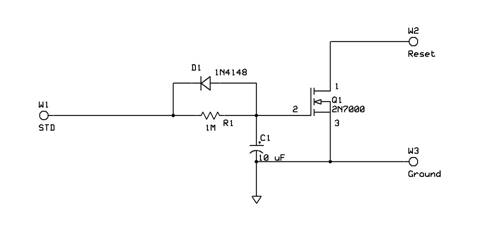
The principle is that the STD signal on the 8870 DTMF decoder used in the RC-210 repeater controller (and others) will always go to a logic high state when a DTMF signal is decoded. This will occur in almost all cases, regardless of whether the CPU it is connected to has gone out to lunch or not. When the logic high is applied to the W1 connection point, the current flow through R1 will charge C1. Q1 is a MOSFET and as such has a very high impedance input allowing such high values of resistance to accommodate the long delay desired. After about 8 to 10 seconds C1 will charge to a sufficient level to turn Q1 on effectively connecting W2 Reset signal to ground, resetting the attached CPU. When the STD signal on W1 returns to logic low state when no tone is present, C1 will be discharged rapidly via D1. This keeps the STD signals from accumulating over multiple tones, thus requiring the 8 to 10 second time cycle to have to start over at each DTMF signal received.
Installation
NOTE: This circuit and the RC-210 Repeater Controller are static sensitive devices that can be permanently damaged if handled improperly. Use caution and always make sure to discharge any static electricity build up that may occur by first touching the chassis of the controller or some other large grounded metal part of the repeater system BEFORE touching any of the circuits in the controller OR this add-on board.
Here is the board layout. I have tried to standardize the wire colors
as:
W1 = Yellow, W2 = Blue, W3 = Black
Remove power before connecting this circuit to the repeater controller!
1) Attach the Black wire from W3 to the connector near center of the board labeled “Program” and/or “J5” onto pin 6. Note that pin 1 of this connector is labeled on the board and is specifically the front left pin when facing the front of the controller. Also note that the pins number by alternating sides. That is all the odd pins are left to right on the front of the connector 1, 3, 5, 7, 9 and all the even pins are left to right on the back of the connector 2, 4, 6, 8, 10, again while facing the front of the controller.
2) Attach the Yellow wire from W1 to the connector on the right side of the board (while facing the controller) labeled “DTMF Expand” and/or “J8” pin 5 (for port 1 control; port 2 is pin 6 and port 3 is pin 7). Note that pin 1 of this connector is the pin furthest AWAY from you when facing the front of the controller, the rear-most pin. These pins simply count sequentially towards the front of the controller, so pin 5 is the fifth pin from the rear of the board.
3) Attach the Blue wire from W2 to the connector near center of the board labeled “Program” and/or “J5” onto pin 5. See the notes in step 1 for the pin numbering of this connector.
4) Attach the board into the controller chassis by either mounting it through the provided hole with a 4-40 screw to one of the extra posts in the controller OR by using some double-sided sticky tape (non-conductive) and stick it down somewhere in the controller’s case. Make sure there is enough slack in the connecting wires not to pull off or bend the connectors.
5) Once everything is in place, tuck the wires down out of the way so that the lid will not pinch them when it is installed (assuming you have the Arcom case). In any case, verify the wires will not get pinched or dangle into any fans.
Operation:
In operation, sending ANY DTMF (touchtone) digit for about 10 seconds on the port that this circuit is attached to will cause the controller to reset. I usually just press a digit and start counting one thousand one, one thousand two … one thousand ten, and then release the tone pad and the PTT. The repeater will normally stay keyed for a second or two while the CPU goes into reset and re-initializes everything.
Some notes and thoughts on using this:
- Anybody can reset the controller this way, nothing has to be unlocked to enable it. Keep that in mind, it can be good or it can be bad. My thoughts are to tell a few key people about it but don’t talk about it on the repeater where other people that might be malicious could hear.
- I prefer mine on my main repeater port (port one for me) because it is less exposed than having it on the link radio port for example. Ideally it would be on a port that is dedicated to control and is not a part of the repeater or linking system so that you don’t have to worry about the malicious people mentioned above. But it does need to be on a port whose frequency is constant. You wouldn’t want it on a frequency-agile link port and then have to hunt for its last frequency when the controller crashes.
- Never have this circuit “partially” connected. If for example the yellow wire (W1) were left open, the 2N7000 transistor is such high impedance that it would float randomly between a low and high state causing the repeater to reset sporadically.
- Keep in mind that this circuit can reset other things as well. For example on 147.33 I intend to have a second one in my RC-210 but the Reset (blue) wire along with a common ground passed over to my OpenTracker2 that is used for the APRS digipeater at the same site (it is prone to hanging occasionally too).
Acquiring one
Since there was a bit of interest in this circuit, I had a circuit board made and acquired the parts to build some up. Even though I run a business doing consulting work, I am not in the business of selling things. So I am keeping this strictly on a T&M cost basis and passing them on to you guys for hopefully enough to break even in the end.
Assuming I can send out 25 or so of the assembled boards, I can recover my costs at $20 a piece. Note, this is a completely assembled ready to use board with components stuffed, not a kit. And 25 may be a stretch, so pass this on to others or on forums that you think may be interested.
If you are going to pick it up from me in person, just hand me $20 and I’ll hand you a board. If you need me to ship it to you, mail me $20 plus shipping which currently is $5.80 (or whatever the USPS “if it fits it ships” rate is at the time) along with a printed sheet with your shipping address that I can tape to the box, and I’ll drop it in the mail to you. Any more than that you feel compelled to send will go to the support of the 147.33 Skywarn Repeater (though I am not a non-profit organization so it won’t be deductible).
Sorry, I’m not equipped for credit cards or for any other method of shipping. Now if it turns out that there are 1000+ people wanting these, that may change, but for now at least I’m just not equipped to do otherwise.
To get by mail:
Send $20 for the assembled board (ready to install) plus $5.80 (or current rate) for shipping to:- Steve Mobley – WB4BXO
- 58 Gabbettville Circle
- LaGrange, GA 30240
DON’T FORGET TO INCLUDE YOUR SHIPPING ADDRESS, preferably printed out on a piece of paper I can tape to the box.
To pick up in person:
Shoot an email to wb4bxo@mindspring.com
Please do not contact me on the air about acquiring one. Though some may contend it would be legal since I am not making any money on it, I still don’t think it would be ethical and as such, I intend to be very careful about it over the air. I have loved ham radio too long to jeopardize my license over it. Thanks for your understanding on that.
73 and tnx de WB4BXO